In the following, the geometric proportioning of flat double-layer grids (FDLGs) and double-layer braced barrel vaults (DLBBVs) as related to their design is discussed:
1. Common Configuration
To simplify fabrication of spatial structures, very few different sizes are usually used. Since most buildings have a square or rectangular plan, here only buildings with these plan shapes are considered. In practice, the top or bottom layer is mostly considered to have a diagonal configuration (the most popular is square-on-diagonal). The diagonal-on-larger square offset or diagonal-on-diagonal configurations can be the optimum choices (in particular when supports are placed at the corners only). However, when the building plan is not rectangular but made of rectangular segments (such as with re-entrant corners), the square-on-square offset or the square-on-larger square offset is more commonly used.
For the DLBBVs the most efficient (least weight) configuration is square-on-square offset.
Considering the overall costs of spatial structures, the configurations with the least number of members and joints (connectors) are usually the most economical choices.
2. Module Size
It is usually more economical to design spatial structures with large module sizes. As a general rule, with an increase in the module size, fewer components are required for a given area, the structure becomes lighter (more efficient), and as a result more cost effective. In most cases, the type and spanning length capacity of the decking or cladding defines the spatial structure module size. The module size is also limited by the purlin spacing, which in turn depends on the type of cladding being used. For example, a maximum spacing of 5 ft is used for acrylic pyramids, 9 ft when using aluminum decks, 5 ft for glass reinforced plastic (GRP), and 1.5ft for polycarbonate
sheets. Steel decking has the largest allowable span of about 15 ft.
However, for most practical purposes the member length is limited by the ability of the workers to assemble the structure (usually a maximum of 9ft long). For longer members, equipment such as cranes will be required to hoist and help with the assembly, resulting in higher construction costs. In addition, a large module size requires very large member sizes due to the susceptibility of compression members to buckling. When aluminum is used instead of steel, the spatial structure has to be deeper to compensate for the loss of material stiffness.
The module size also depends on location and type of supports, orientation, repetition, type of joints, and space needed for mechanical/ electrical equipment placement within the frame.
Geometrical Proportioning of a Flat Spatial Structure (Square-on-Square Offset)
Geometrical Proportioning of a Double-Layer Barrel Vault (Square-on-Square Offset)
The module size (a) for commercial systems ranges between 4 ft - 12 ft with a typical size of 5 ft - 7 ft. The optimum module size for flat double-layer grids must satisfy the following relationship: 0.7d < a < 1.8d (corner-supported), 0.9d < a < 1.3d (edge-supported). The most typical depth (d) is 0.707a (bracing are at 45 degrees), for which the bracing and module size have the same length, when square-on-square offset configuration is used. See the animation below for an explanation of the variables.
3. Span/Depth Ratio and Bracings’ Inclination Angle
For preliminary design of flat double-layer grids (FDLGs) the optimum span/depth ratio (s/d) can be assumed as:
corner-supported spatial structures = 5~11
edge-supported spatial structures = 7~15
It has to be noted that the above s/d ratios result in the least weight structures. These values can be larger if the number of modules are increased. Span/depth ratio of 20-40 for edge supported and 15-20 for corner supported FDLGs can be achieved. Also, cantilevering FDLGs by about 15% to 30% can increase the optimum span/depth ratio to 25.
The angle of inclination of the bracing members has an effect on the distribution of stresses and the deflection of the DLG. The shallower the bracing members (smaller the inclination angle), the larger are the stresses and maximum deflections.
For corner-supported FDLGs the optimum angle of inclination of bracing members is 37~63 degrees, and 46~57 degrees for the edge-supported structures.
Definition of Angle of Inclination
For double-layer braced barrel vaults (DLBBVs) the optimum span to depth ratio varies between 10-30, depending on whether the structure is corner or edge supported, and the number of modules (the larger the number of modules, the larger the optimum s/d ratio).
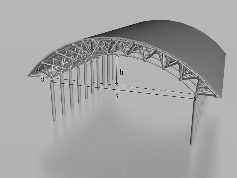
Geometric Proportioning of a Double-Layer Braced Barrel Vault
The optimum rise/span ratio (h/s) for corner-supported circular DLBBVs is 0.20, and 0.40 for the edge-supported systems.
In general, the smaller the span/depth (s/d) ratio, the stiffer (smaller deformations under the loads) the structure is. Also, the larger the depth to module size (d/a) ratio, the stiffer the structure. In addition, the larger the number of members to the number of joints, the more indeterminate and stiffer the structure.
4. Efficiency
To design an efficient (least weight) flat double-layer grid (FDLG) spatial structure, a triangular or square plan with supports along all edges and a 10~15% cantilever is recommended. This results in the smallest member forces and least structural weight. Using cantilevers can result in substantial reduction in member sizes. They do not have much effect on the size of bracing members (not much change in the transferred shear to columns) but can result in less deflection and material and more uniform stress distribution as long as their length is less than 30% (corner supported) or 15% (edge supported) of the back span. An ideal FDLG has a square, triangular or other polygonal plan shape with continuous perimeter edge supports and 10~15% overhang.