|
<< 1 2 >>
The spatial structure configuration is usually selected based on the total applied loads and support locations.
For the case of flat double-layer grids (FDLG) with the top layer members in compression and the bottom layer in tension, it is more efficient to select configurations with shorter top layer members. This is due to the fact that compression members are susceptible to buckling.
The configurations used for the different layers of spatial structures do not necessarily have to be the same. The most common configurations of spatial structures, defined by pattern tessellations can be divided into four groups: A. Rectangular Grids; B. Diagonal Grids; C. Rectangular/Diagonal Grids; and D. Three-Way Grids. Group A includes Square-On-Square, Square-On-Square Offset, and Square-On-Larger-Square-Offset configurations. Group B consists of Diagonal-On-Diagonal, Diagonal-On-Diagonal Offset, and Diagonal-On-Larger Diagonal Offset patterns. Group C includes Square-On-Diagonal Offset, Diagonal-On-Square Offset, and Diagonal-On-Larger-Square-Offset configurations. Group D consists of Triangle-On-Triangle ,and Triangle-On-Triangle Offset configurations.
A. Rectangular Grids
- Square-On-Square: In this case the top square grid is directly above the lower square grid and the bracing members are in vertical planes only. The plan view of this system shows the top layer only.
- Square-On-Square Offset: The top layer is offset with respect to the bottom layer by one-half module size. This is the most common configuration used for spatial structures, however, it is less efficient than the Square-On-Diagonal Offset. This system is more efficient for structures with relatively short spans and few modules. Square-On-Square Offset configuration is usually used when the loads are very large and the structure is continuously supported along all edges.
- Square-On-Larger Square Offset: This configuration is created by removing some of the bottom layer members (usually in tension) and the attached bracings of the Square-On-Square Offset at a rectangular pattern. The lower layer members in this case have twice the length of the upper layers. Due to the addition of the openings, this system is more suitable when the architect intends to provide more natural lights inside the building (skylights can be placed within the openings). This system is usually selected for structures subjected to normal range of loads with supports along all edges. The forces in the lower layer are nearly twice as much as the upper layer, however, since these members are in tension they are obviously not susceptible to buckling.
B. Diagonal Grids
- Diagonal-On-Diagonal: This configuration consists of two layers of diagonal grids(at 45 degrees angle) placed directly above each other and connected by bracing members. Similar to the Square-On-Square configuration the plan view of this system shows the top layer only.
- Diagonal-On-Diagonal Offset: This configuration consists of patterns that are at 45 degree with the edges. It is created by turning the members of Square-On-Square Offset by 45 degrees. This configuration is usually selected when the perimeter of the spatial structure has to match the building edge, the loads are large, and the structure is supported at the corners only.
Most architects and engineers have not been aware of the cost savings potential of using this configuration. This configuration provides a distinction between the edge lines of the spatial structure and wall lines of the building. To keep the symmetry, the number of modules along both directions must be in multiples of two.
- Diagonal-On-Larger Diagonal: This configuration is created by removing some of the bottom layer members at a regular pattern. The structural behavior of this type of grid is similar to the diagonal-on-diagonal.
Diagonal-on-diagonal or diagonal-on-larger diagonal FDLGs are better choices when the supports are placed at the corners only, even though it is usually more difficult to place the mechanical ducts and pipes through due to the diagonals density.
C. Rectangular/Diagonal Grids
- Square-On-Diagonal Offset: In this case the top layer is a square grid and the bottom layer is made of a diagonal grid (at 45 degrees angle). As in the previous cases, the bracing members connect the top layer nodes to the bottom layer nodes. The Square-On-Diagonal configuration with supports at four corners only, results in large member forces along the edges.
The Square-On-Diagonal is usually the most optimum spatial structure configuration both in terms of the use of materials (weight of structure) and structural performance. This is particularly true when the structure is used as large span flat roof system with the total dead, live and snow loads considerably larger than the uplift wind forces.
In terms of use of material or weight of structure this system is more efficient than the Square-On-Square Offset as it has fewer members (about one-half the bracing members and fewer bottom layer members). The lower layer members are longer (by a factor of  ), and since these members are usually in tension, this configuration is desirable for large span horizontal or sloped roof structures. ), and since these members are usually in tension, this configuration is desirable for large span horizontal or sloped roof structures.
The Square-On-Diagonal Offset usually uses about 80% of the material for a square-on-square offset. The selection of the configuration becomes more important when the structure has a span of over 100 ft, and can have a significant impact on the total cost of the project.
Architecturally, the square-on-diagonal is more appealing than the denser square-on-square offset system as there are more openings. In addition, the square modular pattern of top layer is ideal for the use of many types of cladding materials such as glass, acrylic skylights and metal decking. This configuration is stable only if the outer modules along the edge include bracing members.
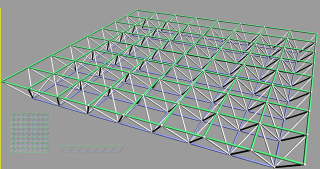 Square-on-Square Offset FDLG Square-on-Square Offset FDLG
|
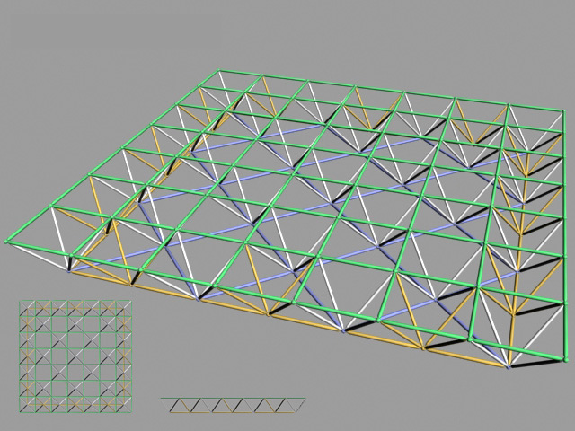
Square-on-Square-Diagonal Offset FDLG
|
- Diagonal-On-Square Offset: This configuration consists of a diagonal grid as the top layer and a smaller square grid as the bottom layer(offset with respect to the top layer). The bracing members connect the nodes of the two layers to each other. It is not as efficient as the square-on-diagonal offset configuration.
- Diagonal-On-Larger Square Offset: This configuration is created by removing some of the bottom layer members of diagonal-on-square offset at a regular pattern, creating a more efficient (lighter weight) configuration or fewer and longer tension members (not susceptible to buckling) are used.
D. Three-Way Grids
- Triangle-On-Triangle: This configuration is made of two similar triangular grids directly on top of each other, connected together by bracing members. This provides a very rigid system capable of resisting large loads. The plan view of this configuration is a three-way grid.
- Triangle-On-Triangle Offset: This configuration is made of two offset triangular module grids for the top and bottom layers. The nodes of the lower grid triangles are directly below the center of the upper layer triangular modules and the diagonals connect the upper and lower nodes to each other. The three-way grid provides a strong system, which can be made of identical interconnected members.
<< 1 2 >> |